Check out my music: https://soundcloud.com/playinmyblues

Sunday, 18 June 2017

Raspberry Pi User Group, June 17, 2017

Happy Father's Day to all the fathers out there, and their families!

Today is also the day of the Johnny Miles marathon and we still have runners going by the house. Lots of the energy there!


Raspberry Pi User Group Meeting, June 17, 2017
Place: New Glasgow Library, New Glasgow, NS


Arduino / Python Serial Communications Using PySerial:

We had a Raspberry Pi User Group Meeting yesterday, June 17th. I was working on my robot yesterday. I am working through some tutorials on YouTube about Arduino and Python Serial Communications. I had looked up a number of tutorials online and worked through a couple of them. However, whenever I tried to do something that expanded on the ideas presented, it never worked. That is why I did some more searching and found the topic above.

Here is a link to the first video of a good set:
https://youtu.be/KB67cuaEJOU?list=PL5YMW87TmMmUBdNSM7dDS3-1WLwEUkhFU

These videos are short and very relevant to how I want to use an Arduino and a Raspberry Pi Zero Wireless together on my robot. To make things really simple, I am using a USB cable to interface Arduino and Python. For testing and learning purposes, I am using a PC running Ubuntu with my Arduino. Using Linux and Arduino really cuts down on prototyping time as the programs compile and upload very quickly with such a system. It also works fairly quickly to actually develop on the Raspberry Pi Zero W but, there it time to go back and forth between the RPi and a PC to view any kind of web-based tutorials.

By the way, this topic uses PySerial and works with Python 2 and Python 3.


The Robot:

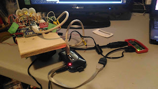
This is my robot in its current state:

This is a mess of wires! However, if you take the time to look through the wires,
you can see the USB Boarduino in the middle, the photocells are to the left setup as voltage dividers with the resistors in the breadboards. The new additions as of late are the H-bridge motor drivers on what is the front right and right side of the robot. I placed the RPi Zero W and a USB hub to give an idea of what is to be added. It looks like I will have to add another layer to the chassis to fit the other devices. I might also add a 16x2 LCD and some push buttons. Once I get it going, I will consider refactoring it by soldering together some permanent circuit boards for the H-bridge motor drivers and the photocell/resistor voltage dividers to free up the solderless breadboards.


Underneath are the geared motors with wheels, the battery pack with
rechargeable batteries, and the swivel caster wheel. The battery pack is held in place with two elastics. You can also see the IR sensor on the bottom that will allow the robot to be line-following. It is not hooked up yet as I have not made it light-following yet.
 The motors work and so do the photocells. I need to normalize the three photocell/resistor voltage dividers to allow for easy programming of signals going to the motor drivers. That way it will follow light uniformly for light shone on all three photocells.


PAW Server:

For a change in direction, and possible use on a robot at some point, we checked out running a web server on an old Android phone. I chose a tutorial on the PAW Web Server which is a simple app that runs on Android without having to root the device. It has some excellent features but keep in mind that a single-core 800 MHz, 512 MB RAM device will not run much at blazing fast speeds.

All the same, it is fun to use a webcam server, robot text-to-speech, and of course, serving up actual webpages. There is too much to describe but it looks very useful and the interface is very easy to use. Just search for tutorials on the PAW Server and you should find something to guide through orientation.


List of Topics To Date:

Here is an updated list of things we have worked on or covered in some way, to date:
  • Raspberry Pi radio - your own little FM broadcaster!
  • Command line music players and how to use them to edit music files
  • FlightRadar24 - watch airline data
  • How to set up your RPi the first time
  • Minecraft Pi workshop - programming in Python to make your own custom Minecraft game
  • How to make an LED turn on and off using Python and RPi General Purpose Input/Output (GPIO) pins
  • Free RPi material such as magazines and short books provided by "The MagPi" magazine
  •  Setting up your own private LAN (not Internet accessible). This is useful for places where organizations keep their own Internet Accessible LAN locked down. This means you cannot do simple things such as using SSH to login into your RPi. If you set up your own private LAN, you can connect both your PC and RPi and login remotely using SSH.
  • Run a servo motor using Python.
  • RPi 3 as desktop PC replacement - would do if that was all you had but, not really recommended.
  • RPi 3 - 3.5 inch touchsreen
  • Starting to explore Arduino/RPi Zero W USB communications (same as Arduino/Python Serial Commuinications)
  • Forward/Reverse Relay modules
If you would like to see something specific covered, drop me a line! You can also drop by the meetings once they resume again in September, 2017.

Wednesday, 7 June 2017

Raspberry Pi Zero W and Arduino Robot, June 7, 2017

Here is a quick post to show the current state of my robot. It is currently to the point where I have all the necessary components except maybe the transistors necessary to make H-bridge motor drivers for each wheel. I have transistors that might work but have not built an H-bridge to test them. I am using geared motors, a USB Boarduino, an RPi Zero W, some mini solderless breadboards, a powered USB hub, three UBEC's that supply 5V, 3A, some photocells, an 8-cell AA battery pack with rechargeables and a homemade chassis from plywood.

The photo shows everything running from AC/DC adaptors at moment. However, everything has been tested with homemade USB power cables. I just hope I do not make the mistake of plugging in the positive and negative of those USB cables into the same connection. I saw a recent product that offered the same power from a USB port that ran the power connections out to red and black shrouded alligator clips. The tweet said an accident waiting to happen!

Current state:

At the moment, with the programs I am running, I can send a number from the RPi Zero W by USB to the Arduino and have the Arduino light up and LED that number of times. The next stage is to use directional controls commonly used in video games, W, A, D, and S, to light up the LED's. I would also like to be able to adjust the brightness according to how long I hold down the directional key using PWM on the Arduino.

That way I know the current setup is ready to accept a more fully developed program that will accept both directional controls using Python on the RPi Zero W as well as using the photocell light sensors. Keep in mind, PySerial is used.
After finding a number of different tutorials on using PySerial with an Arduino, here is the one I found the most useful (easiest to use and mod to my purposes):
http://www.instructables.com/id/Interface-Python-and-Arduino-with-pySerial/

My apologies if the code does not copy correctly. I copied and pasted the code into Blogger then edited it where needed. Here are the two programs I am using to control the LED's at this time:


Python code:
# program: control_arduino_leds.py
# This program sends data from the RPi over USB to an Arduino and receives
# that data back - repeated. The data sent to the Arduino controls the number
# of times the LED's light up on the Arduino.
# The pair program for the Arduino is receive_from_pi_light_leds.ino
from time import sleep
import serial
ser = serial.Serial('/dev/ttyUSB0', 9600) # Establish the connection on a
# specific port

counter = 7
# testing number, 48 is the character 0, zero, 57 is 9
# Below 32 everything in ASCII is gibberish
try:
  while True:
    ser.write(str(chr(counter))) # convert the decimal number to ASCII then 
                                 # send it to the Arduino
    print "counter = %d" % counter
    print ser.readline() # read the newest output from the Arduino
    sleep(0.5) # delay from 1/10 seconds
    if counter == 255:
    counter = 32

finally:
  ser.close() 

Arduino Sketch:
// program: receive_from_pi_light_leds.ino
/* This program receives data from the RPi over USB and sends data back. Before
 * sends the data back, it calls a function to light one or more LED's according
 * to the data received. 
 * PAIR PROGRAM on RPi: 
 */
int led1 = 13; // led is connected to digital pin 13 
int led2 = 12;

void setup() { 
  pinMode(led1, OUTPUT); 
  pinMode(led2, OUTPUT);
  Serial.begin(9600); // set the baud rate
  Serial.println("Ready"); // print "Ready" once
}

void loop() {
  char inByte = ' '; if(Serial.available()) { // only send data back if data has been sent
  char inByte = Serial.read();  // read the incoming data
  light_leds(inByte);
  Serial.println(inByte);  // send the data back in a new line so that it is $
                             // all one long line
  }
  else if(!Serial.available()){
    stop_go();
  }
  delay(100);
}

void light_leds(int n) {
  for(int i = 0; i < n; i++) {
    digitalWrite(led2, HIGH);
    Serial.println("inside light_leds");
    Serial.println(char(i+48));
    delay(500);
    digitalWrite(led2, LOW);
    delay(500);
  }
  Serial.println("light_leds END");
  delay(3000);
  Serial.println("going to stop_go");
  stop_go();
}

void stop_go() {  // does nothing at this point
}

Sunday, 4 June 2017

Raspberry Pi User Group Meeting, May 27, 2017

Next Meeting:    June 17, 2017, 10am - 2pm @ New Glasgow Library
Check out Kijiji.ca New Glasgow, NS for current ads.

Unfortunately our date had to be changed from our regular Sunday to a Saturday due to the library closing on Sundays halfway through May to the beginning of September. We did have the new date posted on our Kijiji ad but the message did not get out to some people - sorry about that.

There was some time at the beginning of the meeting where I was by myself. I took the time to work on my robot. Connecting the photocells was the first job. I had one photocell connected more or less the way I wanted by the time the first attendee arrived.

Here is the robot with just the photocell (light) sensors and one solderless breadboard, and wheels with geared motors. The screws for the third wheel (a caster wheel) can be seen in three places. To start with, I originally used a screw that was too long for the job. Grounding it down so it would not interfere with anything that might be placed on that section of the robot was too much trouble. Although I left the one ground down screw in place, I went and bought the correct length screws for the rest of the caster wheel mounting holes.


Here are is the robot with LED's connected so that they light up according to which sensor has the most light shone upon it. The LED's are on the far side of the board behind the light sensors.


Our attendee had some modules he wants to use to construct his model train environment. We started off with a forward-reverse relay module purchased from eBay. These modules were from China but had some decent documentation in English. Once we started to work with them, we figured it out. We also found the eBay listing for the same module and watched the video which was close-captioned in English. Watching it in action on the video helped.

One interesting thing we found was that the model train power supply was not not appropriate to run the relay modules. One of them just would not power up. Luckily, we had an Arduino board from which we used the power supply. So, if you are into model trains or interested in getting started with model trains, make sure you have at least one good power supply to test your equipment.

Here is the link to the module:
http://www.ebay.ca/itm/2x-DC-5V-6V-8V-9V-12V-Motor-Forward-Reverse-Time-controller-Delay-Relay-Module-/331638809913?hash=item4d3736a539:g:kCkAAOSwLpdW~JR3


In the case of testing the relay module, we did not provide a load to switch on so we only had to worry about the current and voltage necessary to run the module electronics used to determine the timing for the forward-reverse cycles. We did not have to worry about the power supply for a motor or how to hook one up. We could hear the relay switch when it powered to indicate it was working.


When borrowing the power supply built into any board, you should have a quick look to see what the power supply circuit can handle. You can do this for Arduino by going to the Arduino website and looking for the relevant board. Look for the hardware schematic. For an Arduino from 2009, the voltage regulator is an MC33269. One of the key properteis to look at when reading the data sheet is the maximum current supplied by the particular device. In the case of the Arduino board, you should also check for Arduino documentation to see if there is anything specific done to the voltage regulator that allows for less or more current than normally supplied by the voltage regulator. Do a web search on the part or go directly to the manufacturer's website to find their data sheet. There are also some sites that provide data sheets from most manufacturers.

We had another module to search for: a servo motor shield. This was easy as it gave the manufacturer on the Arduino shield, what is was, I cannot recall. Do a websearch on "Arduino motor shield" and you will come up with a number of results that will likely serve your purpose. If the websearch provides you with an acceptable result, you should be able to find a relevant tutorial.

Come see us at the library Saturday, June 17, 2017 to see what new things we are using and troubleshooting. The robot should be able to follow light by then! If you look closely, you can see that there is actually no RPi on the robot yet! Give it time.